Intro
My home lab lives in a closet. - It’s not ideal, but it’s what i’ve got.
Originally, when we designed that part of the house, the room was meant to be a “storage room”, and as such, i had all the ethernet plugs routed to a panel in the wall of this room. A year later our youngest son came into this world, and along with his arrival he claimed the room as his.
Prior to his arrival i had everything on open shelves, and the room kept a steady 22C. As toddlers and electronics rarely mix well, i had to do something else, and not wanting to face rerouting everything to another location, i ended up with the easy/cheap solution, to replace the open shelves with a closet.
While anything that generates serious amounts of heat, like my NAS, has been moved out a long time ago, a few things still remain that requires cooling and are not so easily moved, namely a couple of Ubiquity EdgeSwitch 8 port devices, and a Ubiquity EdgeRouter 4.
To attempt to keep things cool, the back plate of the closet was removed, and a few 80mm holes with covers were installed on top of the closet, along with a series of holes drilled in the bottom of the closet. I thought the natural heat migration would be enough, but without any ventilation the temperature sits around 28-30C, so something had to be done.
Initially i just mounted a couple of 80mm fans powered by a 5V USB power supply, but for a child’s bedroom i found the noise unbearable, so i ended up with a “3 step controllable 12V fan”, running off of a 5V USB power supply. This solution has been running for a few years, and while not ideal, it has kept the temperature in the closet down to around 27C.
Lately i’ve been toying with the idea of putting up a 4-wire PWM controlled fan instead, with a ESP8266 controller coupled with a thermometer to control fan speed depending on the temperature.
Designing the solution
After looking all over the internet for similar solutions i quickly realised The ESP8266 (Wemos D1 Mini) cannot reliably drive a PWM signal at the required 25Khz.. I did a little more searching, and could see others had success using a much lower frequency, all the way down to the default 1023 Hz used on the ESP8266, so i decided to give it a try.
I ordered the parts from my “preferred Chinese vendor”, and the parts list was :
- 1 x Wemos D1 Mini Pro (80/160 Mhz)
- 1 x Arctic F12 PWM, 120mm case fan
- 1 x Wemos D1 Data Logger Shield
- 1 x Wemos D1 DHT Shield
My surveillance solution was originally written to run on Raspberry Pi’s, and requires a timestamp. It’s not exactly a hard requirement, as any message received with a timestamp of 0 will be stamped with the timestamp when it was received by the server. But because i’m using MQTT, there’s no real guarantee when a message will arrive, only that it will eventually arrive.
RTC modules are dirt cheap anyway, and though this particular module i’m using is pretty harsh on the battery, it doesn’t really matter as i use NTP for setting and adjusting the clock every day, and the backup battery is never used.
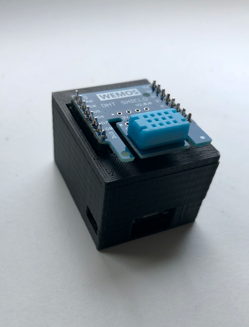
I had the couplers and power supplies in a box somewhere, so i didn’t order those. I also 3D printed a case for it, making it tall enough to contain the Wemos D1 and Data Logger Shield, but leave the DHT shield on the outside to avoid the heat generated inside the case from interfering with my measurements.
I wanted my solution to be able to power off the fan completely in case no cooling is needed. My old solution used a 120mm fan driven by a 5V USB power supply, and it struggled to keep the closet cool, so I settled for a 9 volt power supply after consulting this graph from the fan manufacturers page

A 12V power supply would have be optimal, but according to the chart it’s not possible to turn the fan off via PWM when powered by 12V.
Once the parts arrived, i started tinkering. I ended up with something like the following

Both the RTC and DHT shields are based on I2C, which is somewhat slow, and for a project where every clock cycle matters that may not be optimal. I briefly toyed with ordering different components, but considering the relatively infrequent requests to the individual shields (6 requests per minute), along with the small amount of data being transferred, i decided i would try to make this work.
I chose port D3 for the tachymeter signal, as it has a built in 10K Pullup resistor, which is needed for reading the tachymeter pulse.
PWM Frequencies
The 4-Wire Pulse Width Modulation (PWM) Controlled Fans Specification states
PWM Frequency: Target frequency 25 kHz,
acceptable operational range 21 kHz to 28 kHz
Maximum voltage for logic low: VIL = 0.8 V
Absolute maximum current sourced: Imax = 5 mA (short circuit current)
Absolute maximum voltage level: VMax = 5.25 V (open circuit voltage)

This signal must be pulled up to a maximum of 5.25V within the fan.
Fueled by earlier concerns that i couldn’t drive the fan at the desired frequency, i started experimenting. I was able to drive it successfully at 1Khz, but it gave a weird “buzzing” sound when being run at the lowest PWM setting.
Since the Wemos D1 Mini Pro is also capable of running at 160Mhz i tried that, but sadly that ran rather unstable with coupled with WiFi. The advice was to disable interrupts to make it run reliably, which is probably a bad idea when running with PWM, so i left it at 80Mhz, and kept increasing the frequency.
I was able to run it stable at 18500 Hz, but once i added WiFi, RTC and MQTT, i had to decrease it to 15000 Hz. It still has the odd “failure” where it will increase fan speed for half a second or so until the MQTT operation finishes, but i guess that’s a fair price to pay for getting monitoring.
Coding the solution
I won’t bore you with the complete source listing. If you’re interested it’s available here
I had to figure out a way to dynamically control the fan speed, while operating at the highest possible PWM frequency, and at the same time find enough cycles to read a temperature sensor every n seconds, and report my reading back to my surveillance server, which takes care of the logging/graphing.
I read the temperature sensor every 20 seconds. I could read it more often, but there’s no point as it takes the fan a second or so to spin to the adjusted speed, and it takes time for the increased fan speed to have any effect. I’m guessing that 20 seconds is probably a bit too frequent as well.
As for the actual increases in fan speed, i opted for a 20% increase for every 1C the temperature increases, but adjusted through a floating point number, with the hope that eventually there would be a balance between fan speed and temperature.
Every minute a reading is sent to my surveillance server via MQTT.
Here’s what the main loop looks like
void loop()
{
  reconnect();
  if (abs(millis() - lastmillis) > 20000) {
    if (dht.get() == 0) {
      int pwmVal = minPwm; //20 or so.
      if (dht.temperature > minTemp) {
        pwmVal += ((dht.temperature - minTemp) * (pwmFreq / 5)); //Increase fan speed by 20% for every 1C above minTemp.
        pwmVal = (pwmVal > pwmFreq) ? pwmFreq : pwmVal; //Adjust pwmValue to pwmFreq if above.
      }

      String msg = log_reading(pwmVal, dht.temperature);

      analogWrite(pwmPin, pwmVal);
      Serial.println(msg);
      if (abs(millis() - lastPublish) > 60000) {
        unsigned long pulseDuration = pulseIn(fanPulse, HIGH);
        pulseDuration += pulseIn(fanPulse, LOW);
        unsigned int rpm = (pulseDuration > 0) ? (unsigned int)(1000000 * 60) / (pulseDuration * 2) : 0;
        RtcDateTime now = rtc.GetDateTime();
        String custom = "{\"pwm\":";
        custom += pwmVal;
        custom += "}";
        mqPublish(topicBase, tempProt.reading(hostname, sensor, DateTimeToString(now), dht.temperature, dht.humidity, 0, rpm, custom));
        lastPublish = millis();
      }

    }
    lastmillis = millis();
  }
  mqtt.loop();
}
Safeguards
Nothing much.
- I’ve verified that should the Wemos fail to generate a PWM pulse, the fan will go to 100%, ensuring that things will remain cool, although a bit noisy.
- If the temperature being read is above 30C, another alert will be sent through Pushover.net.
- And finally, should the Wemos fail to report a temperature within 2 minutes, an alert will be sent through Pushover
Results
To be honest i have no idea how effective my old, passive, solution was. I have a cheap USB thermometer installed in the closet, and it’s been showing anywhere from 24C to 28C, depending on the time of day/year.
With this new solution, i have details down to every minute of the day, and graphs showing the temperature, along with the actual fan speed. While the Arduino PulseIn() function may not be terribly accurate, it’s not inaccurate enough to be useless. Just to be sure, i log the actual PWM value along with the reported fan speed.
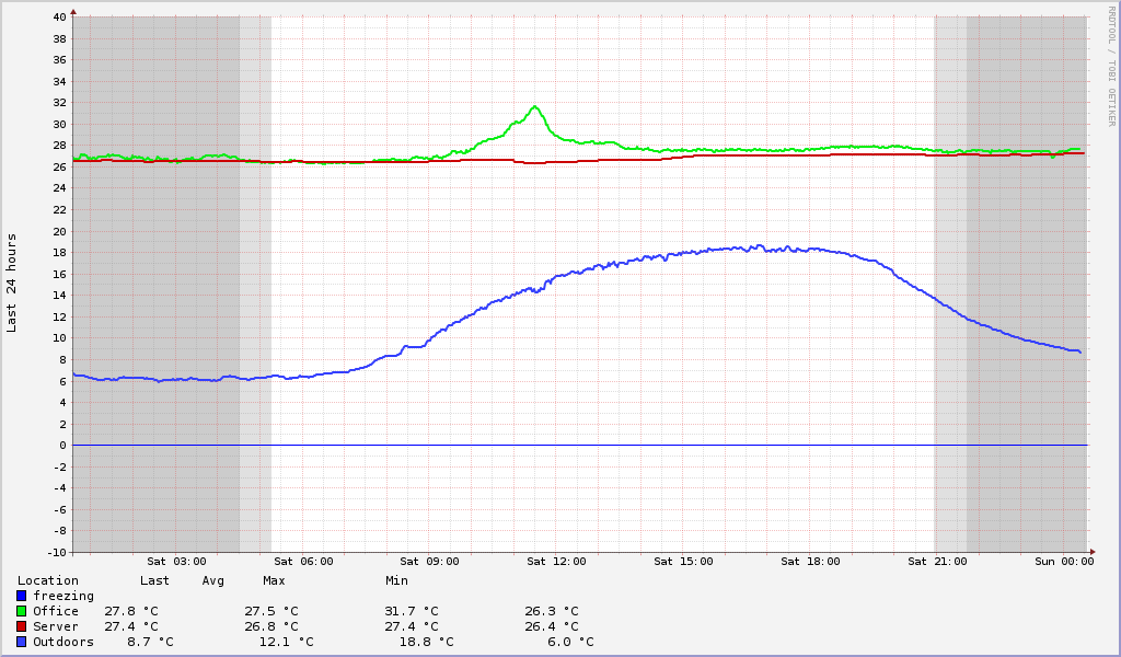
Since installing it, we’ve had a couple of days with 25C or more, and a couple of days with rain, clouds, and 7C-12C temperatures, and I’m happy to report that my “server closet” has been sitting at a comfortable 26C throughout it all. My desired “target temperature” is set to 25C, and represents the temperature where the fan should switch off. It is a value i chose as “acceptable” because it’s close to room temperature, and not too hot for electronics (save a few HDD’s).
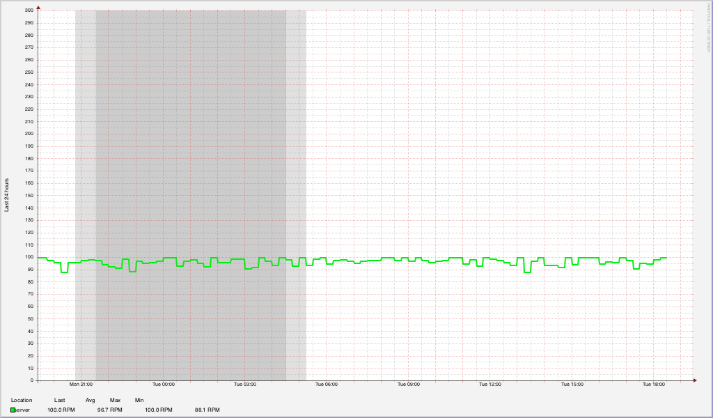
Here are sample graphs a 24 hour period (dusk/night marked by grey shades)
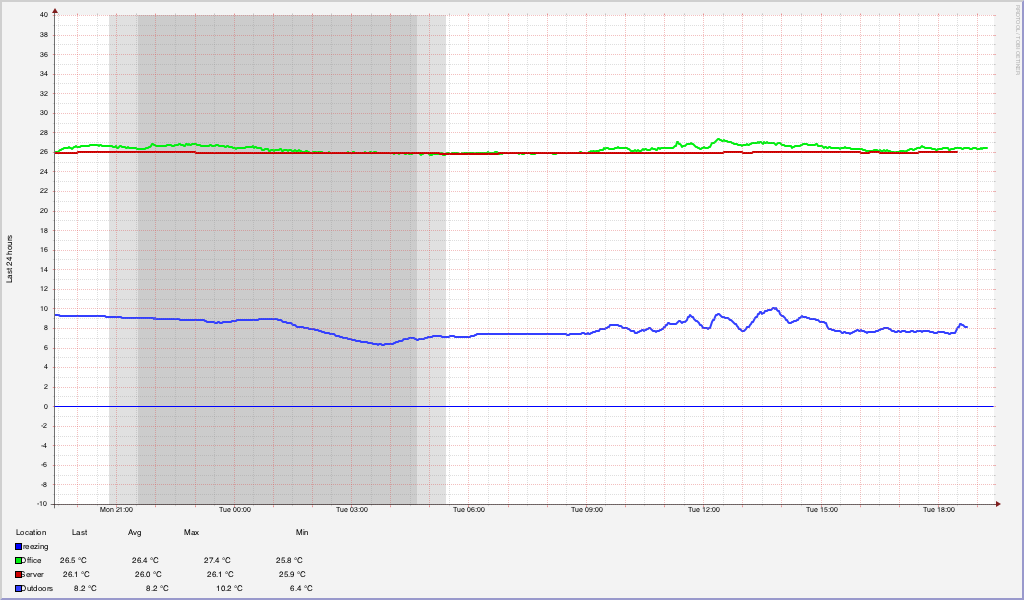
Considering i only have a fan blowing air into a closet, i’m pretty pleased that the temperature inside the closet is virtually identical to the temperature in the adjacent room. In fact it appears to be more stable than the room temperature, fluctuating only around 0.5C.
I doubt the Fan RPM measurement is accurate though since fan speed is adjusted 5 times every minute, but only measured/reported once every minute. From own observations i hear the fan spinning up every now and then, and then it slowly spins down again. Since the temperature never drops below 25C, the fan never stops, but instead runs at ~20% of max PWM value.
I’m currently working on implementing some form of hyteresis to make the fan adjustments somewhat smoother. Once the closet is closed the temperature remains somewhat stable, and is only influenced by fluctuations in the room temperature.
Update
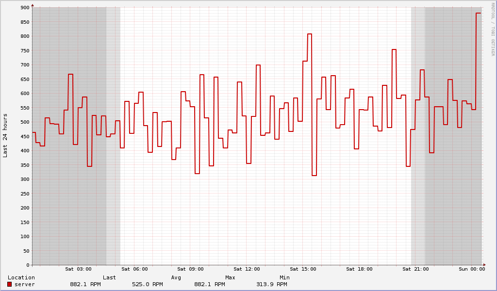
I figured out what i did wrong with the Fan RPM thing. I only used one “PulseIn(Pin, LOW)”. The tachymeter signal is essentially a square wave, and only measuring the LOW side only measures half the pulse. I’ve corrected this to also measure the HIGH pulse. Add them up, and we’ve got the time it takes for half a revolution of the fan.
As for the actual measurement from PulseIn, it’s in microseconds, not in milliseconds as i falsely assumed. I’ve updated the loop code with the new calculation :
unsigned long pulseDuration = pulseIn(fanPulse, HIGH);
pulseDuration += pulseIn(fanPulse, LOW);
unsigned int rpm = (pulseDuration > 0) ? (unsigned int)(1000000 * 60) / (pulseDuration * 2) : 0;
Links
-
Parts
-
Specs
-
Code